PolyWorks Modeler™ Tip
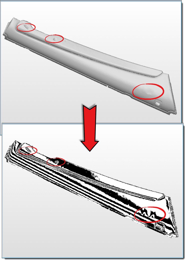
While repairing and optimising a polygonal model obtained from a part that has been dented or improperly cleaned before scanning, you may need more than a sharp eye to detect surface defects. To help locate them, you can use zebra mapping to overlay surfaces with black and white stripes; breaks in their position and orientation emphasise the surface discontinuities. This specialised display mode is easy to use and greatly enhances your awareness of continuity issues.
Step by step: To view a polygonal model in the Zebra Mapping display mode:
1. Make the desired objects visible in the 3D Scene.
2. Choose the View > Zebra Mapping menu item. The Zebra Mapping dialog box displays, and the corresponding display mode is activated.
3. View the polygonal model from different sides and detect surface defects by finding breaks in the position or orientation of the black and white stripes.
4. Optional: Adjust the orientation and size of the stripes using the Zebra Mapping dialog box.
5. When finished, press the ESC key to exit the Zebra Mapping mode.
NOTE: Zebra mapping can also be used to assess the continuity of fitted NURBS patches.