Cooling Strategies for Compressor Cab

Rose Consulting teams with 3D Scanners UK & TotalSim to deliver retrofit cooling options for compressor containment. Using 3D Scanner UK’s geometry capture technology and TotalSim’s unprecedented CFD capability and computing resources, a detailed, as-built, 3D model is used to assess cooling mitigation options without interrupting normal operations.
The National Grid (NG) employs compressor stations (cabs) scattered around the UK in order to supply the National Gas pipeline network. Plant shutdowns to install and test cooling options would be prohibitively expensive.
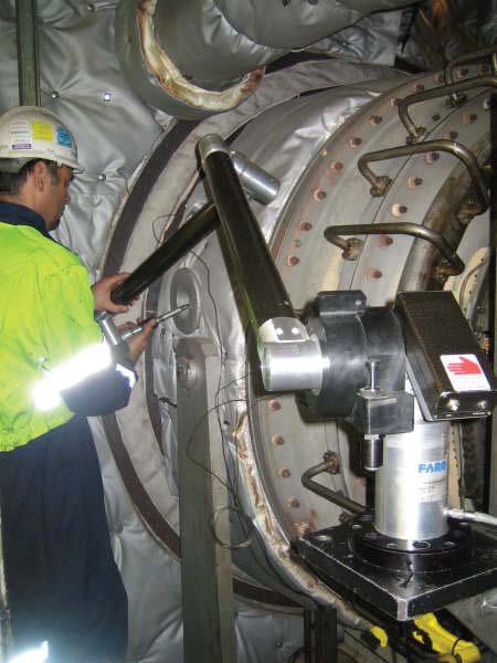
As no 3D cad existed for the cab and internals, the chosen option was a combination of digital photogrammetry and 3D laser scanning.
The points were captured using a V-STARS system and an arm based system for probing detailed areas. V-STARS is a metrology technology that allows you to determine 3D coordinates (XYZ) from digital images. 3D Scanners UK chose the V-STARS system due to the challenging environment. It also offers a quick, but very accurate method of measurement, and the data captured can be used alongside the datum points from an arm based system.
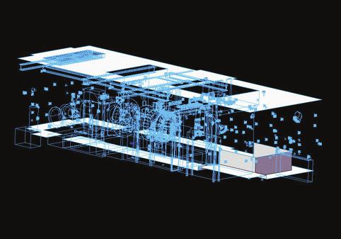
The 3D datum points were then aligned with the V-STARS data within PolyWorks Inspector software. Once aligned, the iges datum points were then imported into SolidWorks software, and used to create a 3D model of the cab.
Below: Detailed measurements with FARO Arm
Below: Points aligned with walkway & ceiling surfaces
created.
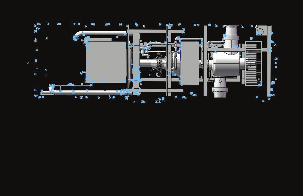
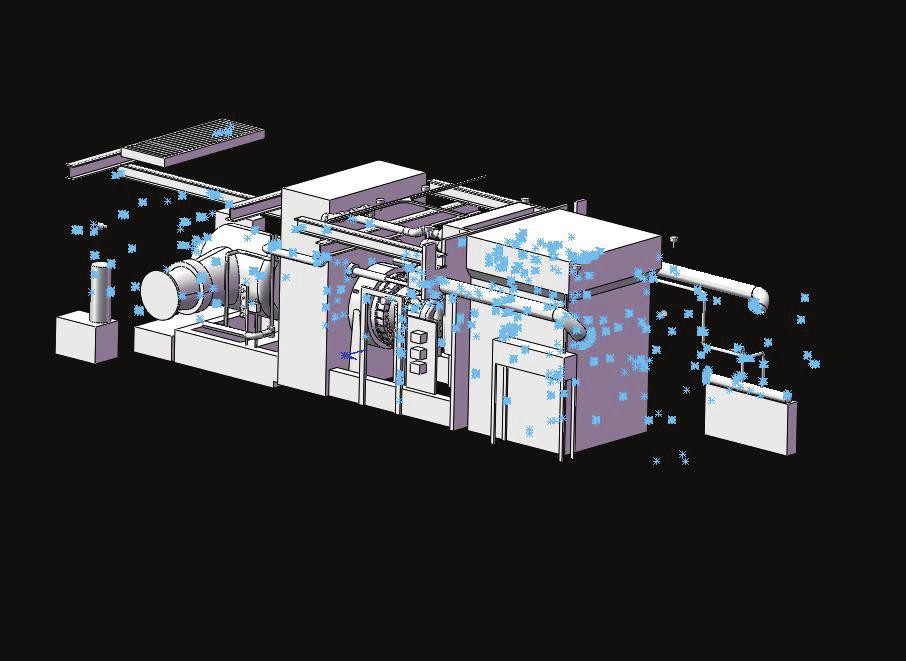
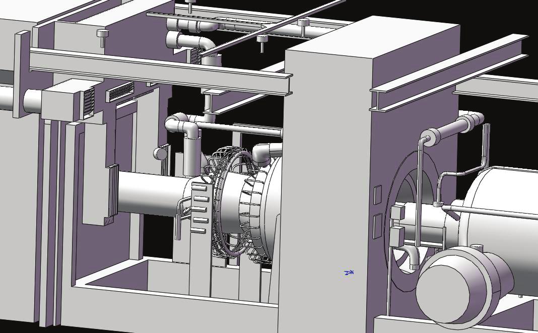
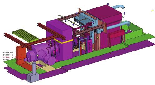
The 3D model included all major equipment within the cab, with increased resolution on the smaller equipment, in the region of the power turbine & the ventilation inlet ducting.
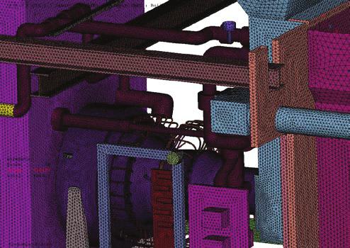
The 3D solid model was then sent to Rose Consulting, where the model was meshed using a predominantly hexahedral mesh of about 13 million cells, with increased resolution in the key areas of flow and heat transfer.
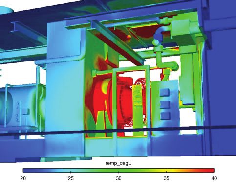
Heat is generated by the machinery within the cab, primarily in the power turbine.
All heat transfer mechanisms were modelled i.e. solid conduction, convection and radiation. Radiation modelling was essential to create accurate predictions, often comprising of 50-60% of the total heat transfer mechanism. Heat leaves the cab through the ventilation exit, the walls and the ceiling.
A previous temperature survey in the cab showed high temperatures near the ceiling, leading to possible cable damage. The baseline CFD model confirmed the presence of this hot ‘footprint’ on the ceiling above the compressor. Various mitigation options were consequently explored. One option was the installation of a heat shield between the ceiling cabling and the compressor.
The heat shield reduced peak ceiling temperatures by about 15% - this could be further improved by increasing the size of the heat shield. A further reduction in ceiling temperatures was also achieved by increasing and redirecting the incoming ventilation air.
Conclusion
CFD allowed a cost-effective, quantitative examination of engineering solutions for reducing in-cab temperatures that risked damaging equipment. More importantly, the approach taken did not interfere with production.
For an accurate and reliable model, good quality data is required - this indeed was achieved by employing the latest technology in 3D scanning in order to capture and accurately model the cab internals. The same geometry and model may then also be used as the basis for gas dispersion & explosion hazards.