Research and Development work for a major OEM.
BMW 320 & Mercedes C220 Front & Rear Suspension
3D Scanners UK were approached by Randle Engineering Solutions Ltd to deliver the following brief:
Requirement 1:
Mounting points, components axes and point cloud data from 2 sets of vehicle front suspensions and a subframe. Measurement data for all of the items listed below need to be extracted as the data is not readily available.
The BMW and Mercedes front suspension contain a very similar set of components.
Mercedes C220 & BMW 320
Pair of lower suspension arms
Steering track rod
Top mount
Spring
- On ground vehicle scan for datums (ground plane, vehicle body, subframe, ride height and wheel centre locations).
- On ramp scan for full RH side suspension assembly scan and datums.
- On ramp scan of partial LH side suspension to aid generation of vehicle centre plane datums, to include wheel centre and lower suspension links.
- Subframe datum positions.
Component axes and datums in global co-ordinate positions within the assembly for the following:
Mercedes C220 & BMW 320
Lower arms
Steering track rod
Wheel centres (in the assembly and also at design ride height)
Subframe mounting locations
Spring & damper axes and locations Also to be supplied – STL Surface data for the assembled suspension components
Assembled scan

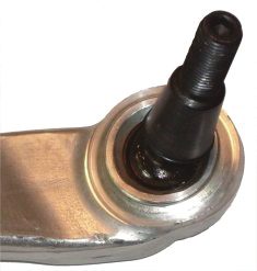
Balljoint locations were measured using the point probe to determine the sphere centres: Rubber gaiter is removed from the ball joint The scanning probe measures 4 or more points on the ball pin sphere. The scanning software then fits a sphere to the 3 points and can deduce the centre of the sphere from this.
Requirement 2:
To carry out a similar programme of work on the rear suspension, as done previously on the front suspension.
The BMW and Mercedes components are as follows:
Mercedes C220 & BMW 320
5 Suspension arms
Knuckle & Wheel Flange
Damper Strut
Anti-roll bar drop link and Anti-roll bar
Subframe
On vehicle scan:
Component axes and datums in global coordinate positions within the assembly for the
following:
BMW & Mercedes
5 suspension arms
Strut including top mount location
Wheel centres (in the assembly and also at design
ride height)
Subframe mounting locations
Spring & damper axes and locations
Anti-roll bar geometry and mounting locations.
Assembled scan of individual components and on vehicle scan:

The Process
The components were all separately 3d laser scanned and probed on site at 3D Scanners. Innovmetric Polyworks software was then used to align and mesh the point cloud data.
A global scan of the components on the car, in ride height position and in the suspension full rebound position (on a wheel free lift), was carried out at the customer site. The components from the two global scans were then meshed at 3d Scanners UK using
Innovmetric Polyworks software to create an STL polygon model.
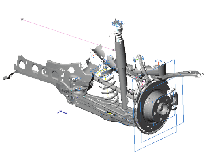
The ride height scan data was aligned over the suspension rebound position scan data, using hard datums that were located on the car body. This allowed Randle Engineering Solutions Ltd to calculate the distance travelled between the two positions. The detailed scans of the individual components were then aligned using best fit, using PolyWorks Inspector, to the same part in the suspension rebound position global scan.
Once the components were aligned, this allowed 3D Scanners UK to extract the data points for the suspension bush centre locations and suspension arm axes that Randle Engineering Solutions Ltd needed.
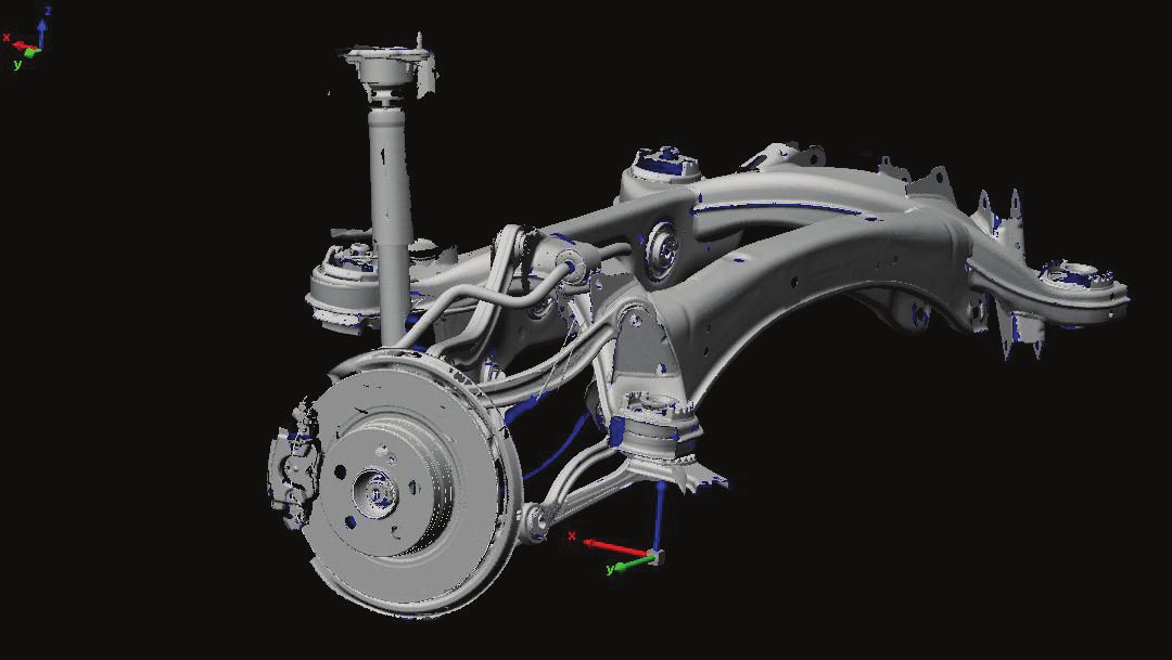
Assembled scan in PolyWorks software


