3D Modelling The Transmission of A King Tiger Tank
Cross and Sansam Ltd & Advanced Tooling Solutions Ltd were approached by private collector Kevin Wheatcroft to manufacture the working parts, from the original parts of a King Tiger Tank. As a result they turned to 3D Scanners UK Ltd to scan and model the transmission.
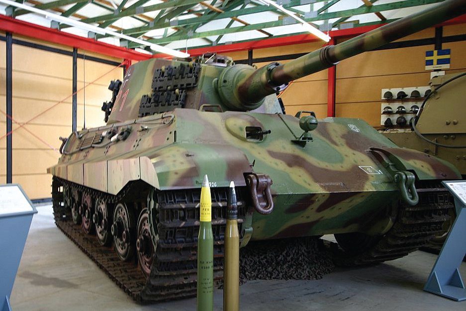
The German King Tiger Tank (predecessor to the Tiger Tank 1) was introduced in early 1944 and was the most powerful and heaviest tank during World War 2. With its powerful 88mm gun and an almost impenetrable 150 to 180mm front armour, it was one of the most feared weapons of the world war 2. Up to the end of the war, the allies had not introduced any eective means to counter the threat.
It was armed with an extremely powerful longbarrelled 88mm gun, even more powerful than that of the Tiger, which red armour-piercing rounds at a muzzle velocity of 1200 metres per second. The length of the barrel itself is over 20 feet long while the rounds weighed almost 20Kgs. It was highly accurate and able to penetrate 150mm of armour at distances exceeding 2200m.
Since the flight time of an armour piercing round at a range of 2200m is about 2.2 seconds or less, accuracy and correction of re against moving targets is more important than with older anti tank guns. This made the heavy predator ideally suited to open terrain where it could engage enemy tanks at long range before the opponent’s weapons were even in range.
Kevin Wheatcroft is a private collector based in Leicestershire, England. He has just started a restoration/rebuild of a complete King Tiger Tank.
The project will include parts from individual King Tiger’s and many parts will also be of new manufacture. Kevin Wheatcroft has stated that he has 80% of the original parts needed for a reconstruction and more parts are sourced continuously.
The aim of the project is, a complete King Tiger Tank in running order.
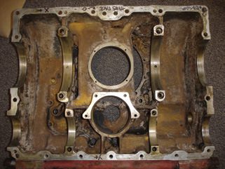
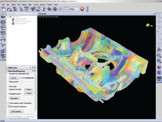
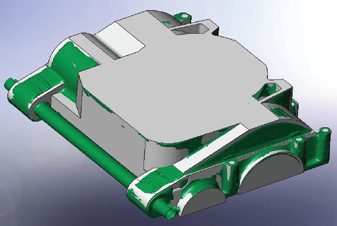
The parts were individually 3d laser scanned & probed. Innovmetric PolyWorks IMAlign module software was then useed to process the scan data. This software automatically aligns the scan paths using the best algorithm to create an aligned point cloud model. Finally the ‘reduce overlap’ functionality is applied to create one unique skin of data points.
Some areas of the parts were impossible to scan because they were out of the line of sight of the laser scanner, but by using the datum’s which were taken whilst probing, the features can be reconstructed accurately in the new part.
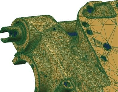
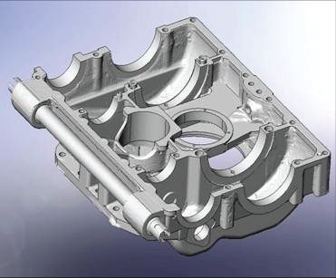
Creating a geometric solid model from a polygon mesh
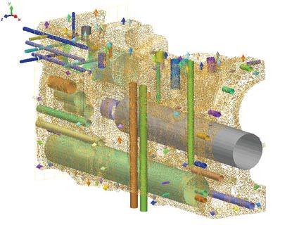
Cylinders and vectors were created within the Innovmetric Polyworks IMInspector module from all of the datums and then exported as a feature. Cross sections were also taken from the .stl mesh in Innovmetric Polyworks IMInspector module and exported as iges curves.
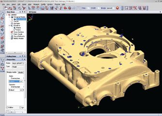
The parts were then modeled separately in SolidWorks software. The .stl mesh of the part was imported into SolidWorks, along with the crosssections and features. A solid model was built from extrusions based on the cross sections, and the holes were recreated from the cylinders and vectors and then extracted from that solid body.
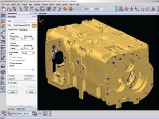
The process was repeated for all the separate parts in the transmission.
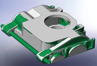
Design modications were then carried out by Advanced Tooling Solutions Ltd in preparation for tooling, before being passed to Cross and Sansam Ltd for hard tooling manufacture.


