A 3D scanning arm, also known as an articulated arm scanner or a portable coordinate measuring machine (CMM), is a versatile tool used for capturing the geometric information of objects with high accuracy. It consists of a multi-jointed mechanical arm equipped with position encoders and various sensors. Let's explore how a 3D scanning arm works:
Arm Design and Construction
A 3D scanning arm is constructed with lightweight yet rigid materials, such as carbon fibre or aluminium, to ensure stability and minimise deflection during scanning. The arm is designed with several articulated joints, typically resembling a human arm, allowing it to mimic natural movement.
Position Encoders
Each joint of the scanning arm is equipped with high-resolution position encoders. These encoders precisely measure the rotation angles and positions of the arm's joints, enabling accurate tracking of the arm's position and orientation in 3D space.
Probe or Laser Scanner Attachment
A 3D scanning arm usually comes with interchangeable attachments, including contact probes and laser scanners. These attachments can be easily mounted at the end of the arm, allowing for different scanning modes and versatility in capturing various types of objects.
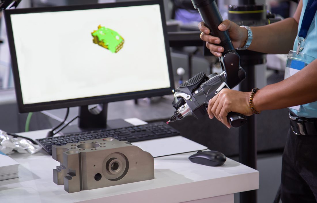
Contact Probe Scanning
When a contact probe is attached to the arm, the user manually guides the probe over the object's surface. As the probe makes contact with the object, it deflects, and the arm's position encoders measure the deflection. This data determines the 3D coordinates of the scanned points on the object's surface.
Laser Scanning
When a laser scanner is attached to the arm, it will project a laser beam across the object's surface. The laser scanner also has position encoders to track its position and orientation. As the laser beam scans the surface, it measures the distance and shape of the object at each point, creating a point cloud representation.
Software Integration and Data Processing
The position and orientation data from the arm's encoders, along with the collected surface measurements, are sent to specialised software integrated with the 3D scanning arm, such as PolyWorks. The software combines the positional data with the surface measurements to generate a precise digital model of the scanned object.
Point Cloud Registration
If multiple scans are required to capture the entire object or to improve accuracy, the point clouds obtained from different positions or orientations need to be aligned and registered. This registration process ensures that the collected data is merged correctly to create a complete and accurate representation of the object's surface.
Mesh Generation and Analysis
Once the registration process is complete, the collected point cloud data is typically converted into a mesh representation, consisting of interconnected triangles or polygons. This mesh can then be used for further analysis, such as dimensional measurements, reverse engineering, or quality control inspections.
Real-Time Feedback
Some advanced 3D scanning arms provide real-time feedback to the user during the scanning process. This feedback may include visualisation of the scanned points, surface deviations, or alignment errors, enabling users to make adjustments or ensure complete coverage of the object's surface.
In summary, a 3D scanning arm utilises position encoders, interchangeable attachments, and specialised software to capture the geometric information of objects. By accurately tracking the arm's position and orientation, combined with the measurements obtained from contact probes or laser scanners, the scanning arm enables precise and portable 3D scanning services for various applications in industries such as manufacturing, design, and quality control.