PolyWorks|Inspector™ Tip
When you probe with a laser tracker using vector adaptors, the location of the resulting measured line features doesn’t match the location of their nominal counterparts, influencing the measurement of Position or Orientation GD&T controls. Starting with PolyWorks® Metrology Suite 2018 IR8, you can change the GD&T calculation zone of axial features from “As Measured” to “Adjust to Nominal Boundaries” in the object properties. In this way, you ensure that Position and Orientation controls for axial features measured outside their nominal boundaries are accurately calculated, and that new pieces are measured in the same way.
Step by step: To adjust a line feature’s GD&T calculation zone according to nominal boundaries:
- Right-click a line feature in the Tree View. The object’s shortcut menu is displayed.
- Click Properties on the menu. The object’s property sheet is displayed.
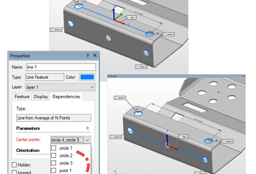
- Navigate to the Feature tab of the Properties sheet and expand the Control section.
- Under GD&T calculation zone, choose Adjust to Nominal Boundaries in thePosition tools and/or Orientation tools lists.
- Click the Apply and the Close buttons.If the feature is measured, its Position and Orientation controls are immediately recalculated using a virtual axis extension within the nominal boundaries only, as shown in the image below. The measured primitive itself remains unaltered.
NOTE: If all axial features are to be measured with vector adapters, you can make theAdjust to Nominal Boundaries method the default calculation parameter for Position and Orientation tools. Simply select Adjust calculation zone to nominal boundaries on theObjects > Features > GD&T page of the PolyWorks|Inspector Options dialog box.