PolyWorks Inspector™ Tip
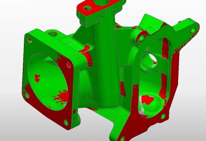
Controlling GD&T form error on the shafts and bores of machined parts requires capturing a large quantity of points, which is a time-consuming operation when using a standard touch-trigger probe. Instead, use the tactile scanning capacity of your CNC CMM to rapidly acquire points for circle, cone, and cylinder features using the desired point density and scanning speed. With this option, you can easily configure circle, cone and cylinder probing to obtain meaningful GD&T form error results.
Step by step: To CNC probe a cylinder feature using tactile scanning:
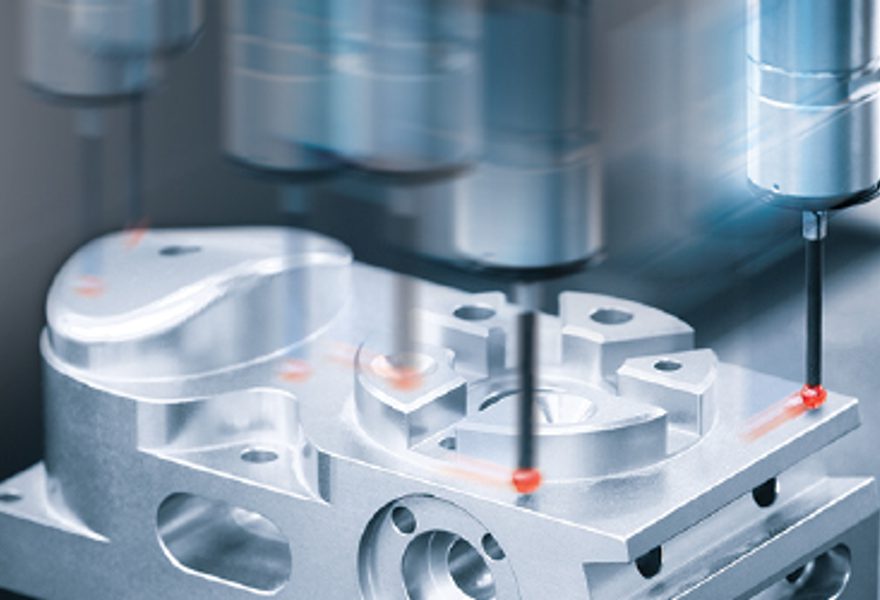
- Set up the CMM with a scanning probe and prepare it to acquire points.
- Create the nominal cylinder feature.
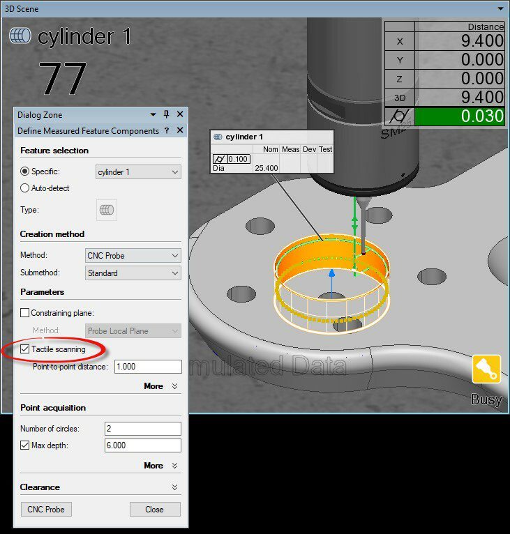
- Right-click the cylinder in the Tree View and click CNC Probe Measured on the shortcut menu that pops up. The Define Measured Feature Components dialog box is displayed.
- Make these specifications:
- In the Parameters section, select the Tactile scanning option.
- Optional: Increase the Point-to-point distance for a large feature, or decrease the value for a small feature, to adjust the number of acquired points.
- Click CNC Probe to launch the tactile scanning operation.
- Optional: To change the tactile scanning speed: Click the CNC Parameters button on the Probing Device toolbar to open the CNC Parameters dialog box, then adjust the Tactile scanning speed value and click the OK button.
NOTE: Tactile scanning is also available in the offline simulation mode.