PolyWorks Inspector™ Tip
When defining a GD&T Position control using a GD&T call out on an engineering drawing, you may not at first see required tolerance zone modifiers in the Geometry Controls pane. To display additional elements, just replace default values by values on the call out, such as the tolerance zone shape. By specifying the correct context, you make quick work of defining your GD&T controls.
Step by step: To define a Position control with a tolerance zone orientation for a slot:
- Right-click over the desired slot feature in the Tree View, or its annotation in the 3D Scene, and click Geometry Controls on the shortcut menu that pops up. The Geometry Controls pane is displayed.
- Click the Add GD&T Control button on the pane’s vertical toolbar. A menu showing the GD&T controls available for the slot is displayed.
- On the menu, click Position. A form to encode the control is displayed, showing default values for a slot.
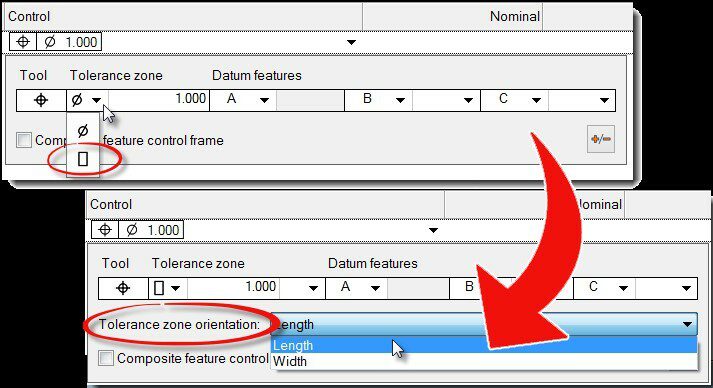
- From the pull down list in the Tolerance zone area, choose Slab-like instead of Cylindrical.
- In the Tolerance zone orientation list that appears, choose Width or Length.
NOTE: The available tolerance zone orientations depend on the type of feature as well as the GD&T tool.