PolyWorks|Inspector™ Tip
When reviewing hole locations, being able to visualise the magnitude and direction of the deviation of the measured primitive centre from the nominal location can help in detecting and understanding manufacturing problems. Starting in PolyWorks|Inspector™ 2018 IR9, you can easily display primitive centre point deviations in the 3D Scene along the X, Y, and Z axes for all point-reducible features. This allows you to show to what extent, and along which axes, holes are deviated so that manufacturing errors can be analysed and corrected.
Step by step: To show primitive centre point deviations in the 3D Scene:
- Make sure a measured hole feature is visible in the 3D Scene
- Right-click the hole feature in the Tree View, then choose View > Deviations > Restore on the shortcut menu that is displayed.
- Click the Object Display Options button on the 3D Scene toolbar. An options list is displayed.
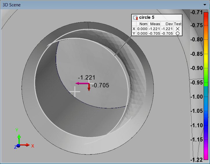
- Navigate to the Features section and set Deviation type to Primitive Centre Points. Based on controlled dimensions set in the Geometry Controls pane, namely X, Y, and Z, up to three deviation vector components are displayed along the standard axes, representing the primitive centre point deviation. As shown in the image, the value for each deviation vector component is represented by its colour, according to the displayed colour scale.
- Optional: To display the numeric value of centre point deviations, select Show deviation values when possible.
NOTE: If X, Y, and Z dimensional controls are assigned a specific coordinate system in the Edit Context dialog box of the Control Reviewer pane, primitive centre point deviations are displayed using the specified coordinate system.


