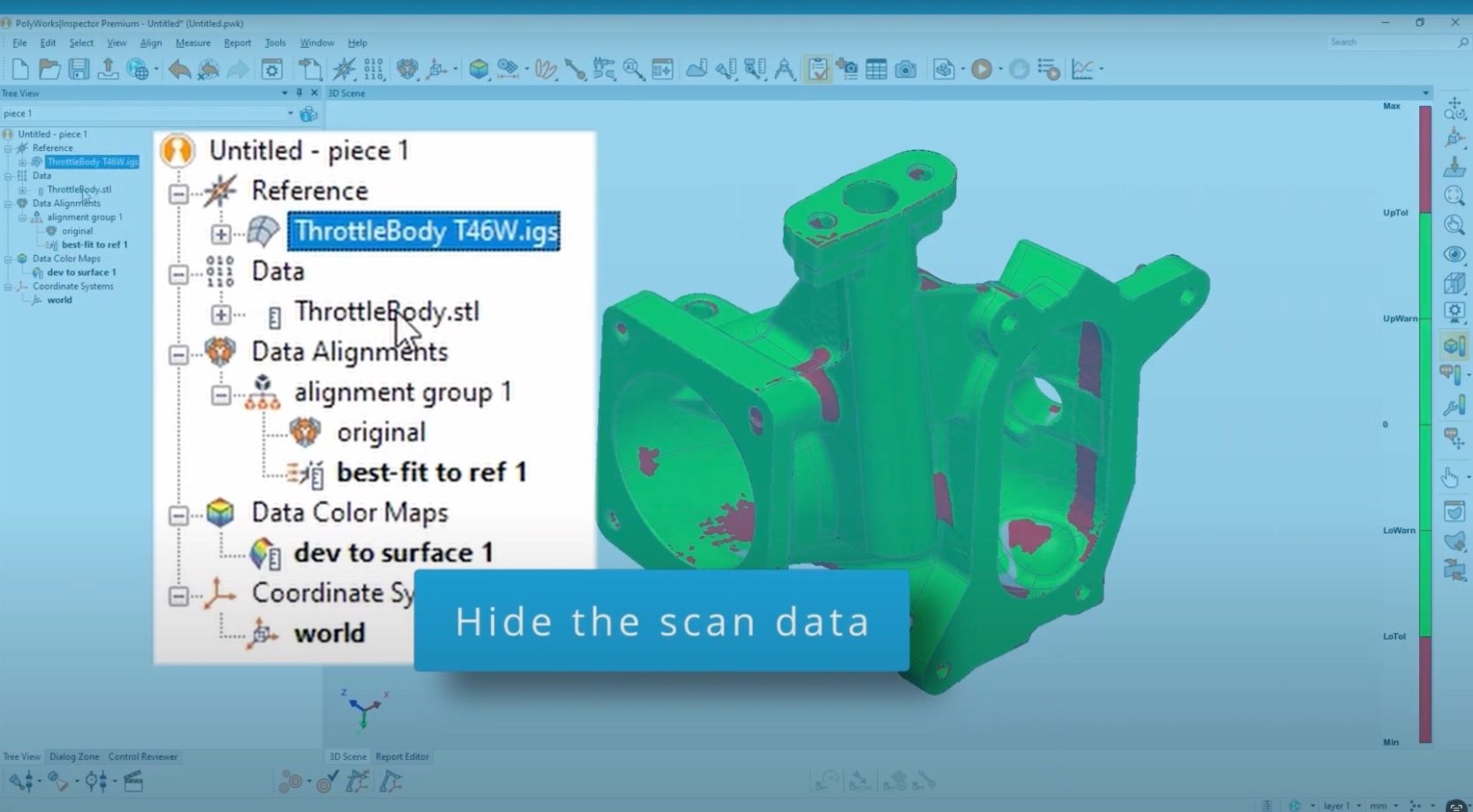
Make quick work of adding specific tolerances to CAD surfaces by following this neat tip, and see a pass and fail colour map of the scan data against the CAD model before your eyes.
1. Hide the scan data
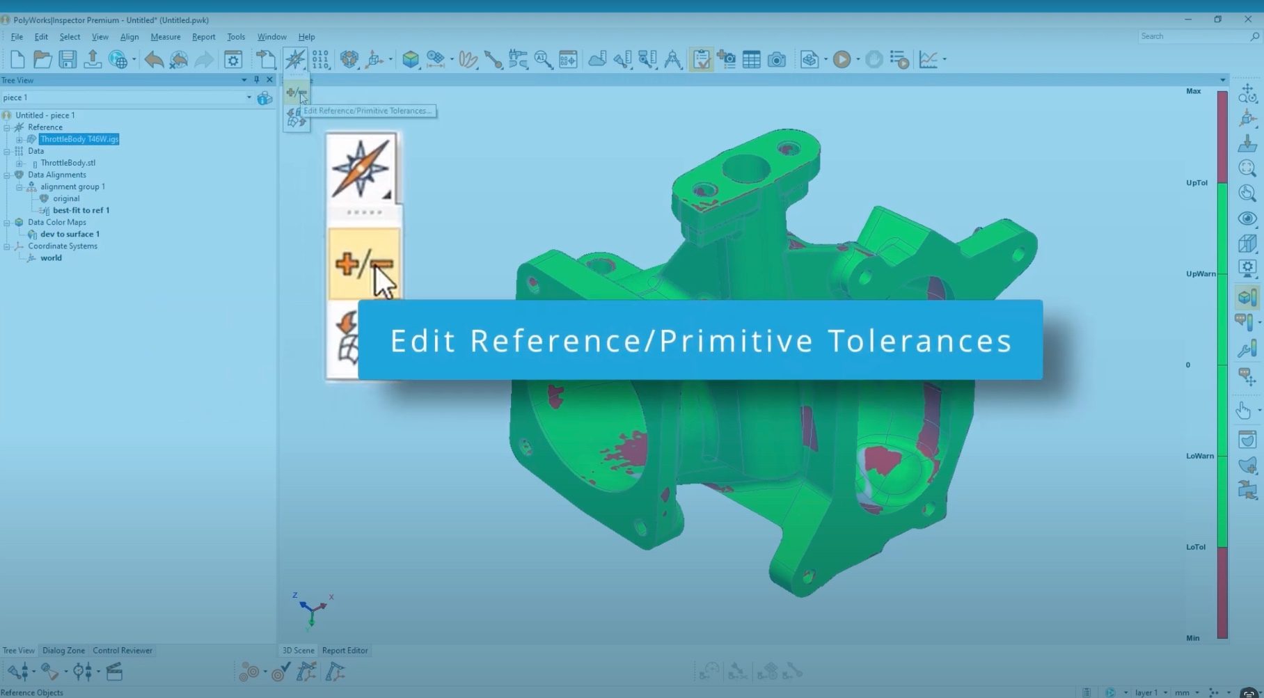
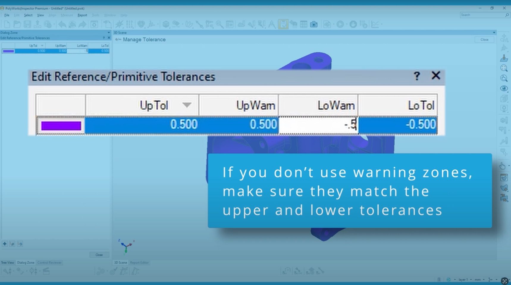
2. Edit Reference/Primitive Tolerances
3. If you don’t use warning zones make sure they match the upper and lower tolerances.
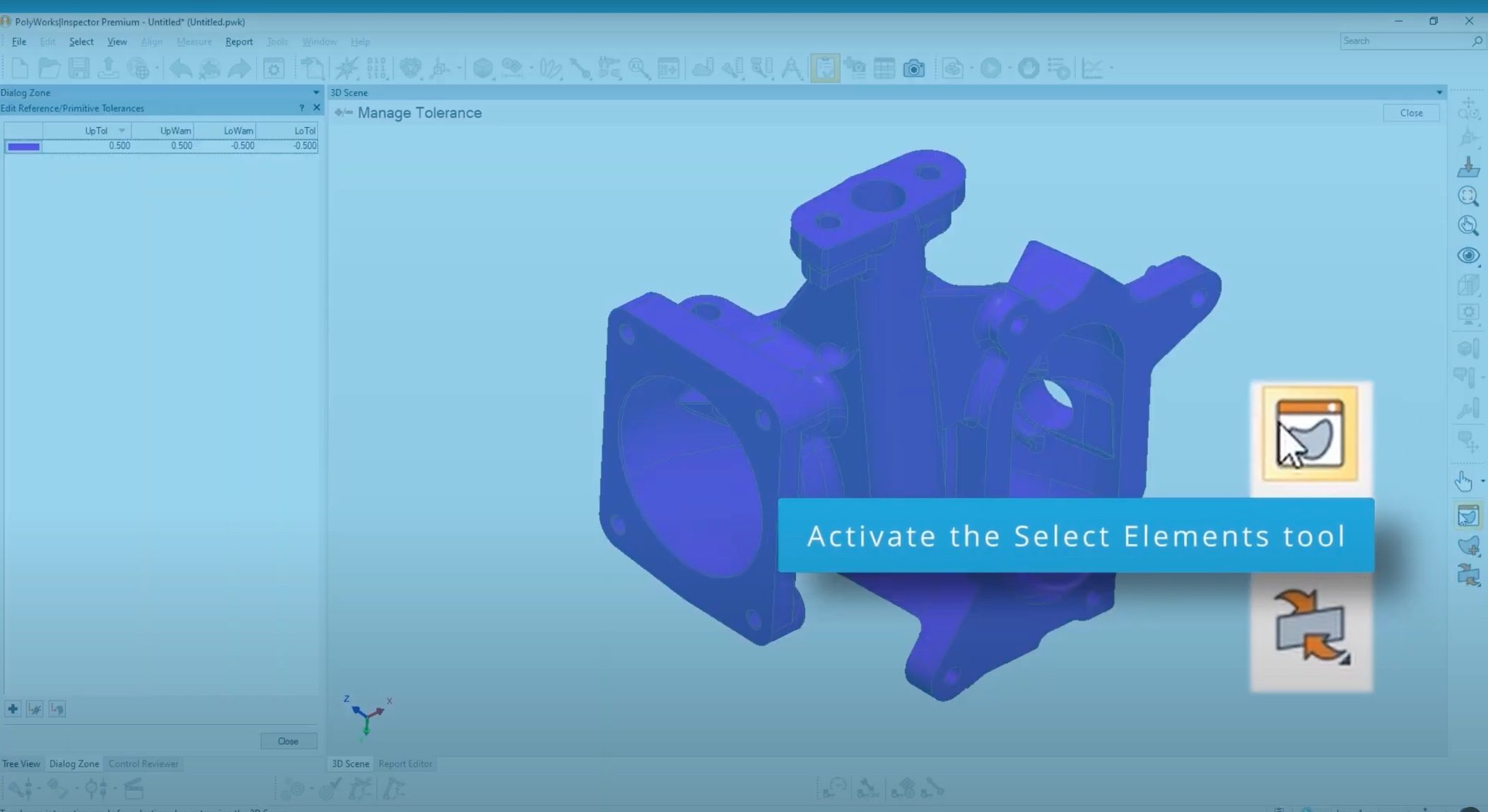
4. Activate the select elements tool
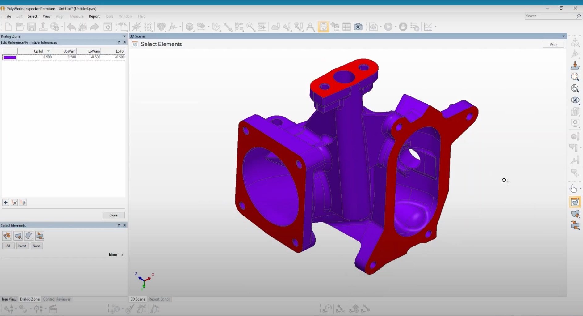
5. Scroll the mouse wheel to reduce the selection area

6. Select the CAD faces with a different tolerance
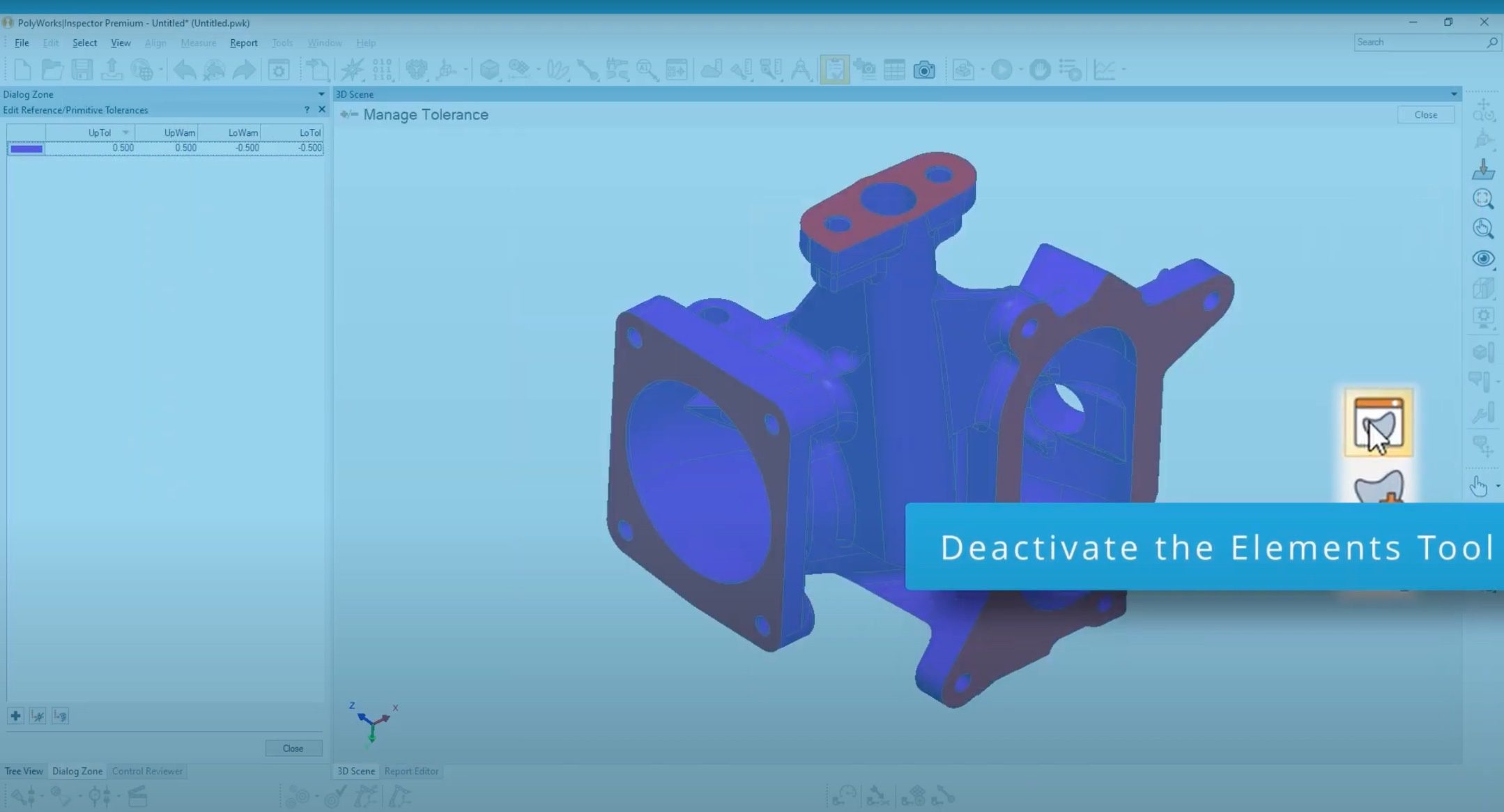
7. Deactivate the elements tool
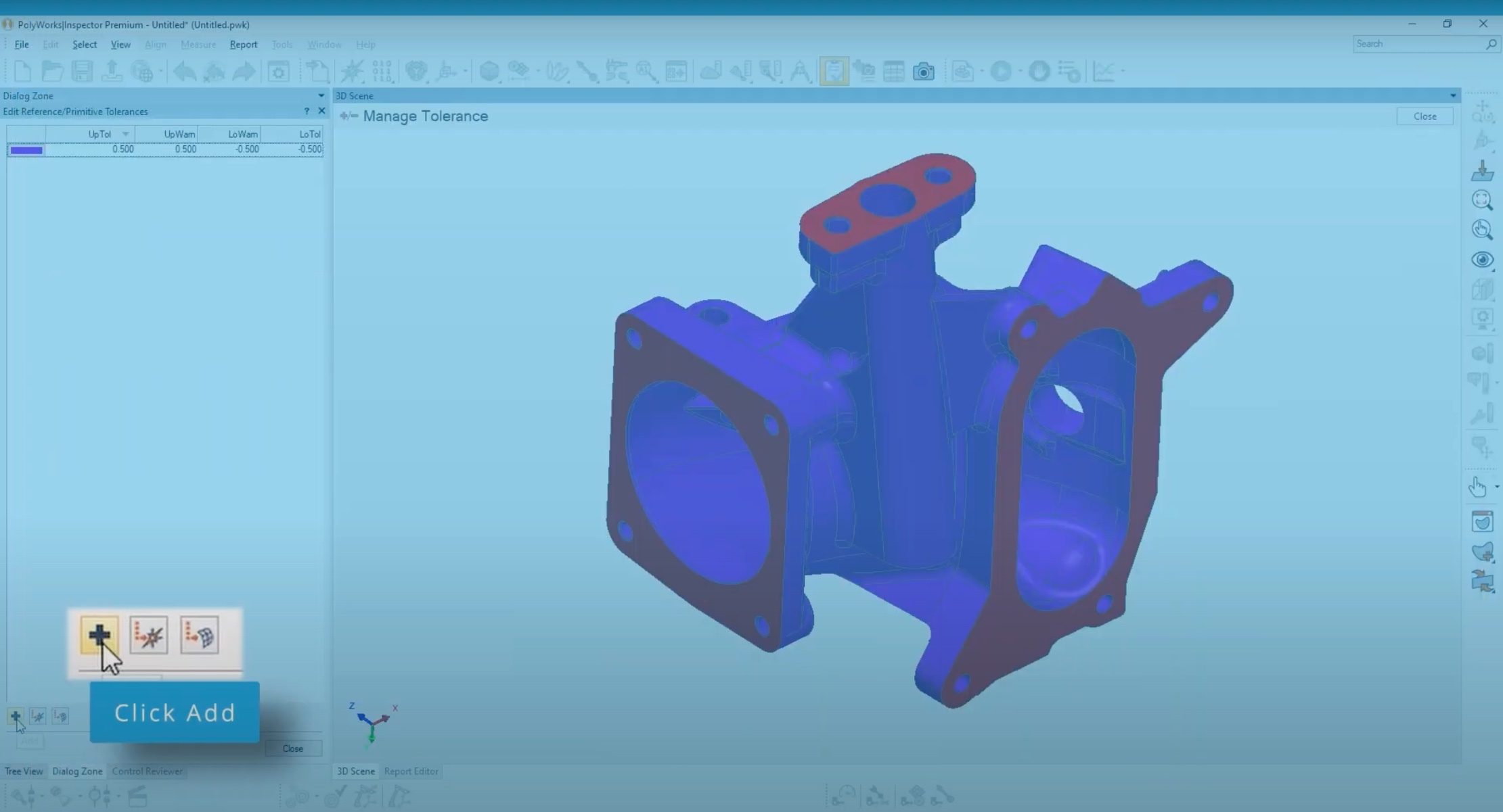
8. Click add
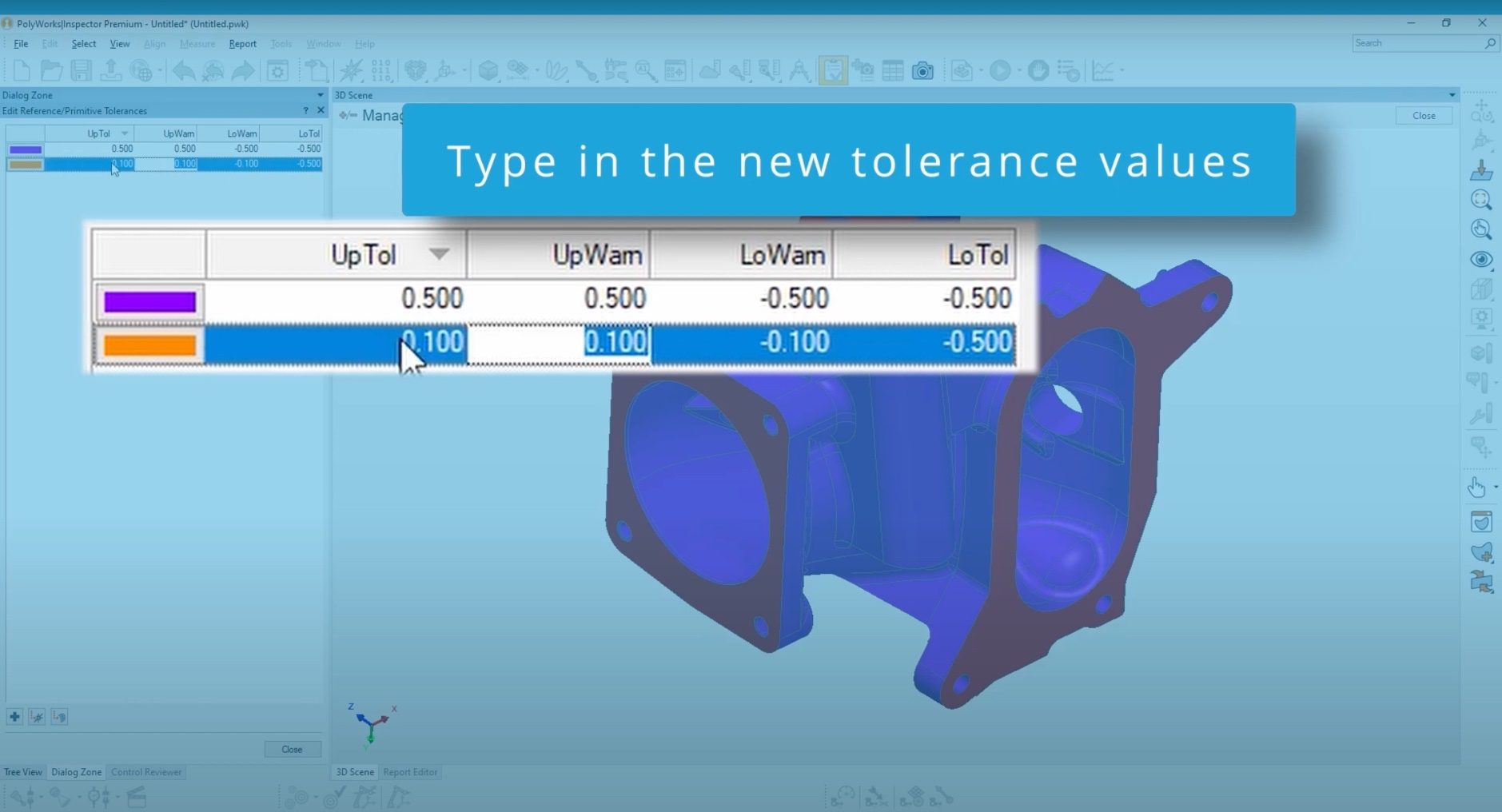
9. Type in the new tolerance values
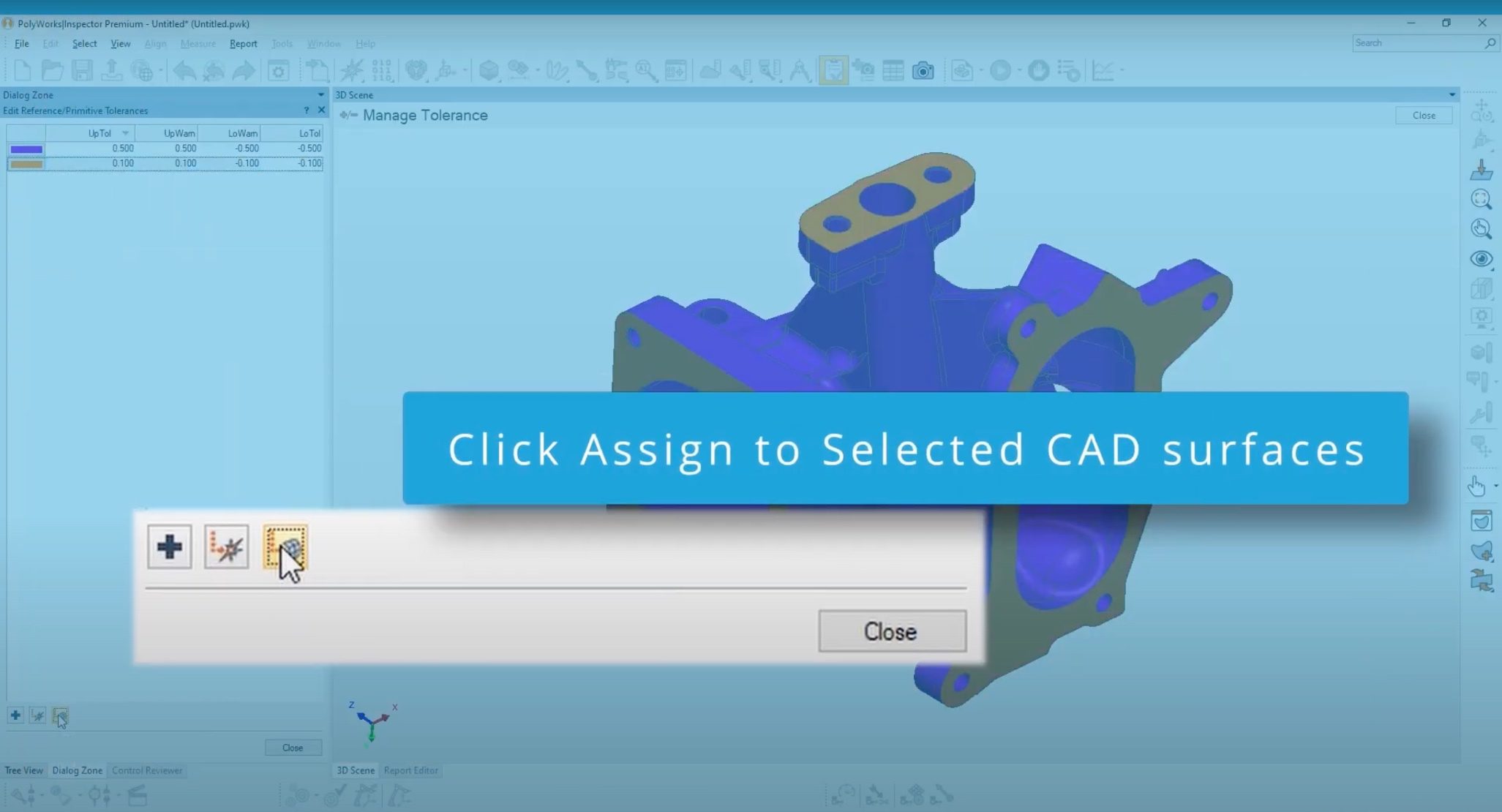
10. Click assign to selected CAD surfaces
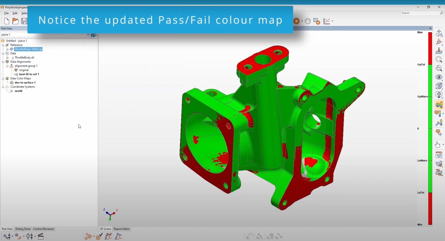
11. Notice the updated Pass/Fail colour map
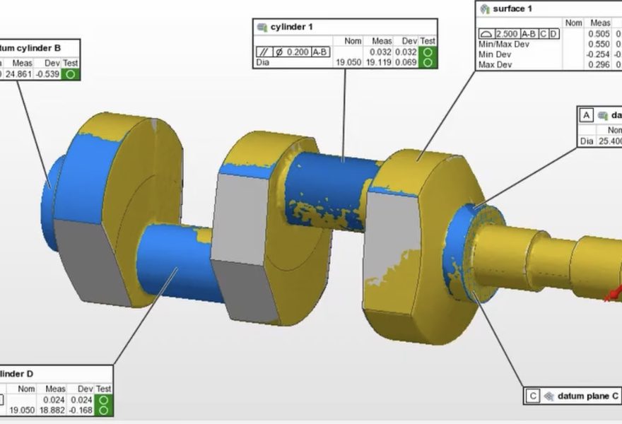
Why add specific tolerances?
Tolerances play a crucial role in the design and manufacturing process of mechanical components. PolyWorks Inspector allows you to define the allowable variation in dimensions and geometric features of a part, which ensures that the manufactured parts meet the design requirements and functional specifications. Without tolerances, there would be no way to ensure that the parts would fit together properly and function as intended.